
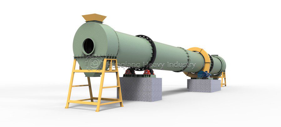
Drum Fertilizer Dryer

Our Services

Have a
project in
mind?

Drum Fertilizer Dryer

The core function of a rotary fertilizer dryer is to remove excess moisture from the material, a process driven fundamentally by the heat source system. The configuration of the heat source system and the optimization of the drying process directly determine drying efficiency, energy consumption, product quality, and operational costs. For fertilizer manufacturers, selecting an appropriate heat source and scientifically setting drying process parameters are key to achieving energy conservation and consumption reduction while ensuring drying quality.
Depending on the fuel type, heat source systems for rotary fertilizer dryers can take various forms, such as coal-fired, gas-fired, biomass-fired, or oil-fired hot air furnaces. Each type of heat source has its own advantages and disadvantages regarding initial investment, operating costs, environmental emissions, and the level of automation. The drying process itself involves the optimized coordination of parameters such as temperature control, airflow regulation, and material residence time. Amidst increasingly stringent environmental regulations and rising energy costs, the rationality of the heat source configuration and the precision of the drying process have become critical benchmarks for assessing the sophistication of a fertilizer production line.

The structure of the equipment

The rotary fertilizer dryer features a scientifically sound, compact overall structure and consists primarily of the following core components:
(I) Rotary Cylinder: The main vessel of the equipment, consisting of a long cylindrical shell inclined slightly (typically 3°–6°) relative to the horizontal. Cylinder diameters range from Φ800mm to Φ4000mm, with lengths customizable based on drying requirements. Front and rear riding rings are mounted on the exterior to support the cylinder’s weight in conjunction with the support roller assemblies; a large gear is positioned in the middle, meshing with a drive pinion to rotate the cylinder. The cylinder is fabricated from high-quality carbon steel plate via rolling and welding, while critical components—such as the riding rings and large gear—undergo integral annealing to relieve internal stresses.
(II) Material Lifting System: Core working components installed on the inner cylinder wall that lift and scatter the material, thereby increasing the contact surface area between the material and the airflow. For high-moisture, sticky fertilizer granules, the system incorporates specially designed lifting flights and anti-sticking devices to effectively break up the material and prevent clumping or accumulation. Common configurations include spiral, lifting, and fan-shaped designs; an optimal combination of these types helps minimize the formation of “wind tunnels” (air bypass channels) within the cylinder.
(III) Drive System: Comprising components such as the electric motor, speed reducer, and pinion gear. The motor drives the pinion through the reducer (which lowers speed while increasing torque); the pinion meshes with the large gear fixed to the cylinder, driving the cylinder to rotate continuously at a low speed. An open-gear transmission design is employed, equipped with protective guards to ensure operational safety.
(IV) Support Assembly: Includes front and rear support rollers and thrust rollers. The support rollers bear the weight of the entire cylinder by supporting the front and rear riding rings. The thrust roller assembly is specifically designed to prevent axial drift caused by the cylinder’s inclined orientation, ensuring long-term, stable operation.
(V) Sealing System: Sealing rings installed at the feed and discharge ends of the cylinder prevent cold air ingress and hot air leakage, thereby maintaining thermal drying efficiency. The well-designed sealing structure effectively minimizes heat loss and dust emissions. (VI) Feeding and discharging devices: These include the feed chute and the discharge section. The feed pipe is inclined at an angle greater than the material’s natural angle of repose to ensure smooth flow into the dryer. A star-type discharge valve is installed at the discharge end to ensure uniform material discharge.

Application scope of equipment

Rotary fertilizer dryers have a wide range of applications.
Fertilizer production: They serve as the core drying equipment for production lines of various granular fertilizers—such as organic, compound, blended, and bio-organic fertilizers—performing the critical task of dewatering and setting wet granules after the granulation process.
Chemical industry: They can be used to dry chemical products such as ammonium sulfate, ammonium nitrate, urea, oxalic acid, PVC, nitrophosphate, and calcium-magnesium-phosphate fertilizer.
Environmental protection: They are suitable for the drying and volume reduction of organic wastes, including sewage sludge, aquatic product waste, food processing waste, and slaughterhouse waste.
Agriculture: They can be used to dry and process agricultural by-products such as straw, forage grass, distillers’ grains, medicinal herb residue, fruit pomace, soy sauce residue, and sugarcane bagasse.
Metallurgy and building materials: They are used to dry mineral raw materials such as fluorite powder, quartz sand, graphite, barite, bentonite, zinc slag, clay, titanium concentrate, coal slime, manganese ore, and limestone.

Types of usable raw materials

Rotary fertilizer dryers can process a wide variety of raw materials.
Fertilizer granules: organic fertilizer granules, compound fertilizer granules, blended fertilizer granules, phosphate/ammonium sulfate granules, etc.
Organic waste: livestock and poultry manure (chicken, pig, cattle manure, etc.), straw, forage grass, distillers’ grains, medicinal residues, fruit pomace, soy sauce residue, sugarcane bagasse, peat, sludge, aquatic product waste, food processing waste, slaughterhouse waste, etc.
Chemical raw materials: ammonium sulfate, ammonium nitrate, urea, oxalic acid, PVC, nitrophosphate, calcium-magnesium-phosphate fertilizer, compound fertilizers, etc.
Mineral raw materials: fluorite powder, quartz sand, graphite, barite, bentonite, zinc slag, clay, titanium concentrate, coal slime, manganese ore, limestone, etc.

The working principle of the equipment

The operating principle of the rotary fertilizer dryer is based on the core mechanism of convective heat exchange between the material and hot air. Its workflow consists of three continuous stages:
Feeding and Dispersion Stage: Wet material is transported to a hopper via a belt conveyor or bucket elevator and enters the higher end of the inclined rotary drum through a feed chute. The drum rotates continuously at a steady speed; internal lifting flights constantly scoop up and raise the wet material from the bottom. As the material reaches a certain height, it falls naturally, creating a uniform curtain of material inside the drum that ensures full contact with the hot air.
Heat Exchange and Dehydration Stage: High-temperature hot air flows through the drum, making full contact with the curtain of wet material as it is repeatedly dispersed and dropped. The action of the lifting flights—constantly raising and scattering the material—significantly increases the contact surface area between the material and the hot air. Through heat conduction and convection, the moisture in the material absorbs heat and turns into water vapor; this dynamic drying process ensures uniform heating of the granules.
Discharge and Exhaust Stage: The dried material moves continuously toward the lower end of the drum under gravity and is discharged from the outlet. Moisture generated during the drying process is promptly extracted by an induced-draft dust removal system and discharged after treatment.

How to operate the equipment

Pre-startup preparation: Conduct a comprehensive inspection of the equipment before every startup. Check the drive components, specifically the belt tension and gear lubrication. Inspect the sealing assemblies to ensure the head and tail seals are intact. Check the hot air system to verify the proper functioning of heating elements and fans. Clear accumulated dust from the air ducts. Inspect the interior of the drum to ensure there are no material blockages.
Startup sequence: Start the drive motor to rotate the drum before igniting the hot air furnace to raise the temperature. Heating the drum while it is stationary is strictly prohibited; doing so causes uneven heating, leading to thermal warping or deformation. Begin feeding material evenly only after the hot air temperature reaches the set value.
Operational monitoring: Operators must continuously monitor key parameters. Maintain negative pressure within the system. Closely observe the drum’s reciprocating movement on the support rollers to ensure stability. Listen for any abnormal noise from the gear mesh (large and small gears). Monitor motor current; an abnormal rise in current indicates an excessive equipment load.
Shutdown sequence: First, stop the material feed; second, shut off the heat source (extinguish the flame); third, stop the drum rotation only after the drum temperature has dropped below 80°C. Shutting down at high temperatures or subjecting the equipment to rapid heating or cooling cycles can severely damage the riding rings and support rollers.

Equipment maintenance methods

Daily Inspections: Observe whether the reciprocating oscillation of the dryer shell on the support rollers is smooth; the contact area between the support rollers and the tire (riding ring) should be at least 70%. Check for abnormal noise during the meshing of the large and small gears. Inspect the sealing rings at both the inlet and discharge ends of the dryer for integrity. Check that the surface temperature of the dryer shell is uniform.
Periodic Maintenance: Check the grease condition of the support roller bearings and drive bearings during every shift; replace or replenish with high-temperature-resistant grease weekly. For new gear reducers, change the lubricating oil after 30 days of operation; thereafter, clean the unit and change the oil every six months. Regularly inspect the internal lifting flights (lifters) for wear and material buildup; excessive buildup increases motor load, so damaged flights should be cleaned or replaced promptly.
Shell Axial Movement Adjustment: After the rotary dryer has operated for a period, the shell may experience axial drift due to gravity distribution; adjust the inclination of the support rollers to maintain the shell’s balance between the thrust rollers.